
Circuitron (the maker of Tortoises) diagrams, which they send upon request, show
connections at I, J and E. My experience tells me that this is exactly what to
do if the turnout is not the first one after the feeder power in a block, or if
there are insulated joiners at G and H, meaning that the point end of the turnout
is the start of a block (a "block" is an electrically isolated trackage section).
In these two cases and in only these two cases do you need three solder
points on your Peco. Remember the main rule of feeder wires given in all wiring books: all feeders must be on the points end of turnouts. A block boundary in the form of insulated joiners (at the points end of your turnout) means that there in no trackage in the block to the points end of the turnout so you must solder on the turnout itself. I and J are the best points to do it for the same reason that E is the best frog soldering point: these points are farthest from vulnerable areas of the turnout. You don't want to melt ties or add solder around throwbars. And after turning over a Peco and seeing the cross-connections underneath the frog area, you don't want to risk melting anything around there either. Which leaves I, J and E as the best candidates. If you're following all this, you can see that flextrack on the points end of the turnout is going to be getting feeder wires so you may as well "strike while the soldering iron is hot"—if I may bend a metaphor—and use these feeder wires in two ways: for track power feeding and frog powering. Obviously, you don't want to solder two wires to each rail at the feeder location (for feeders and to go to the Tortoise accessory switch terminals), so instead, use a butt connector, Scotchlok tap connector, or terminal block connection (or solder under the layout if you prefer) on the feeders before they reach their feed points where they get soldered to flextrack. For appearance's sake, keep wire visibility on top of your layout to a minimum. |
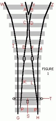

Solder the frog wire (8") to E and the other end of it to contact #4 on the Tortoise.
This is absolute and will happen no matter what. But to see where this comes
from, let's peruse the general rule for frog powering with Tortoises and power-switching
turnouts: When you use Tortoise terminals #2 through #4 for live frog
powering, always solder #4 to the frog, and solder #3 to the rightmost rail
(viewed from the points end) and #2 to the leftmost rail if the terminals on the
Tortoise are facing the points end of the turnout, and if they're not, reverse
which rails are wired to #2 and #3 terminals. Using this method, it's a no-brainer.
Rightmost rail and leftmost rail, above, can be either on turnouts or on
flextrack prior to the turnout, depending on factors just covered. For second and third (and beyond) turnouts after feeders, solder 8" wires at I and J and E and solder E to contact #4, and then apply the rule above to see which (I or J) gets soldered to contact #2 and which gets soldered to contact #3. It depends upon which way you install the Tortoise under the turnout. They work just as well with terminals facing the points end as with terminals facing the frog end. |
